Hardware & Software Design
- Robotic Arm
- DDR Pad
- Stepper Motor
- Graphics Controller
- LED Array
- Overall Software
Robotic Arm
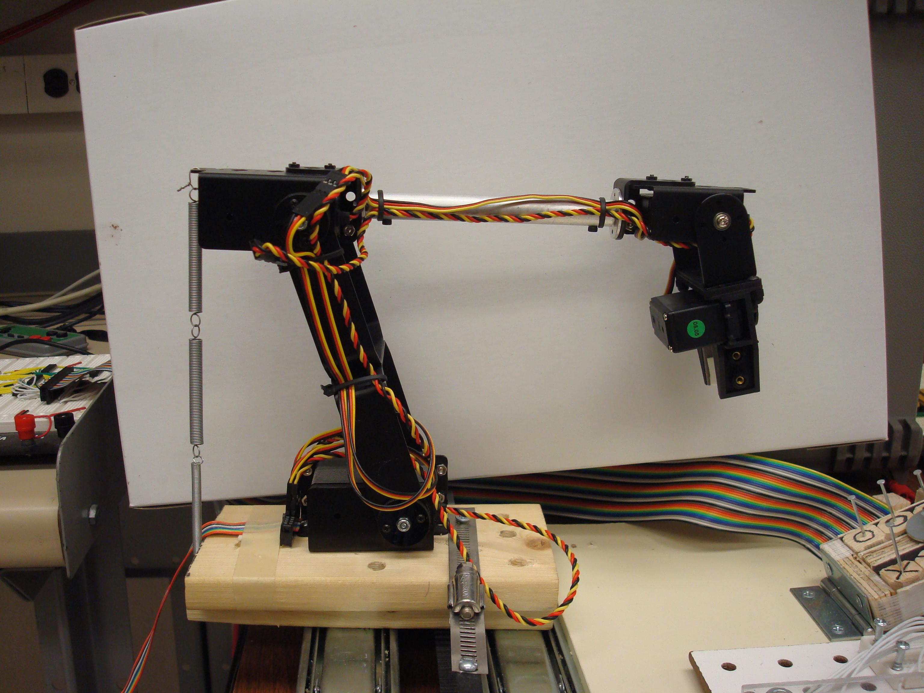
For this project, the robotic arm we used is the AL5D kit from
http://www.lynxmotion.com/Product.aspx?productID=685&CategoryID=133.
The arm consists of four servos: one at the base of the arm, one at the
elbow, one at the wrist, and one to control the pincher. The arm came
with a swiveling base along with a fifth servo that allowed the entire
arm to rotate, but we did not need it for this project.
Hardware
The physical hardware was pretty straightforward. Each servo required
only a ground, a VCC, and a signal wire. The hardware for generating the
pulse signals for the servos (which are pulse-width modulated> was a
little more difficult. One of the challenges I had to overcome with the
robotic arm was to keep the robotic arm from snapping into new positions
instantaneously whenever new pulse signals were sent to the servos.
Therefore, I designed in Xilinx the "smoothifier." At a high level, it
simply ramps up or down the servo pulse widths gradually whenever a new
pusle width value is sent to it. This allowed the robot arm to make more
precise (and less violent) moves. The smoothifier also generates an
active-high "ready" signal that can be polled in software in order to
determine whether the arm is currently in motion or not.
Software
Two of the team members, Abhishek and Tejas, were tasked with
calibrating the robotic arm, which means they write down the values that
each servo must have in order to move to a specific position. After
getting the values from them, I proceeded to write two drivers: one that
simply opens and closes the pincher, and another that takes position
coordinates from the user and writes the predetermined servo values to
the servos, then polls the ready bit of the smoothifier and does not
return from the driver until the movement is complete.
~Allen
DDR Pad
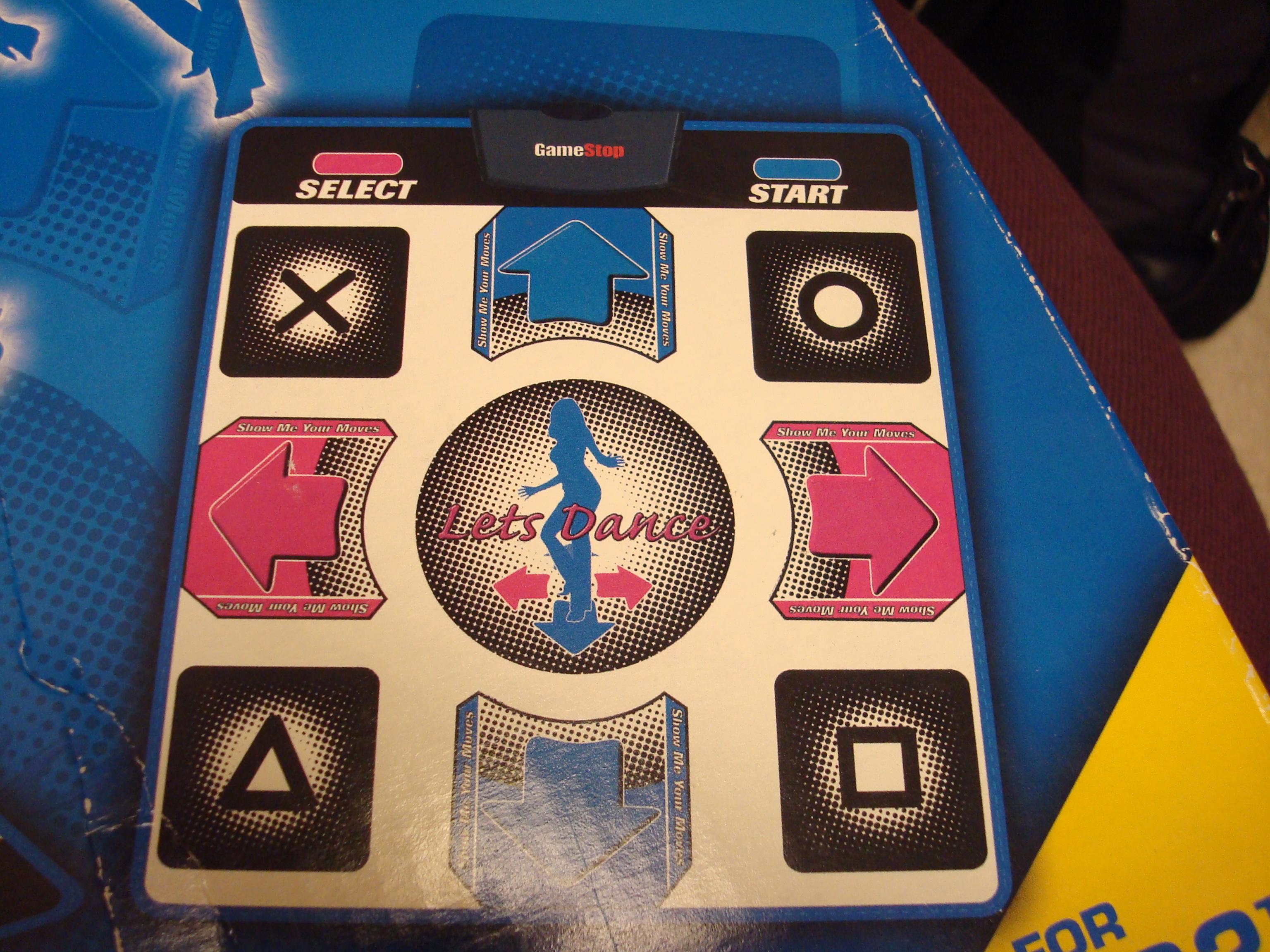
We used 6 pins on the PS2 controller : DATA , GND, VCC, ATT, CLK and
CMD.
Brown - Data: Controller -> PlayStation. The data needs
to be passed through a comparator circuit and then pulled up using 100
ohm pullup.
Orange - Command: PlayStation -> Controller. (Main
Polling Command to
the controller)
Black - Ground
Red - Power: Approximately 3.3 Volts for optimal
performance
Yellow - Attention: This line must be pulled low before
each time the
controller is polled for input.
Blue - Clock: Approximately 200KHz
We got a good head start thanks to the
Brehobber group and
PS2 curiousinventor
as we understood the protocol quickly. Then we generated all the
necessary signals required to obtain DATA from the DDR pad. The DDR
clock speed is about 200 kHz and the clock only runs when the attention
is low. The attention is pulled low whenever the DATA line needs to be
polled. Also every time the attention pulled low, a set of commands(0x1
and 0x42) is sent serially to the controller via the Command wire. Data
is obtained serially and in our case we used shift register to latch the
data. On every negative edge, the data is generated and on positive
edge, it is latched in to the Shift Register. In addition, we also set
up a comparator circuit to improve the quality of DATA and make it more
accurate.
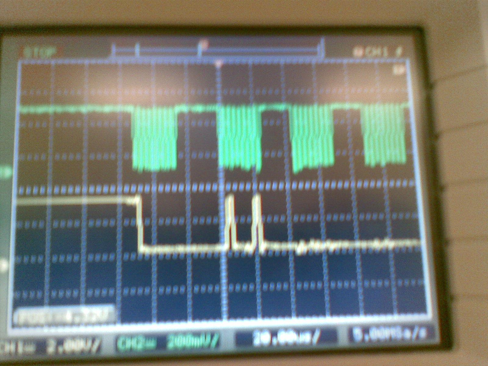
Clock and the Command Signal(0x42)
Hardware
The hardware consisted of many tricky clock dividers as well as many count registers designed specifically to generate the three major signals command, clock and attention that were to be sent to the controller. The command signal was really tricky and took the longest time as it depended on both the clock and the attention. We used global counter to generate the signals so that they are in sync with each other. We also had a shift register to latch all the DATA bits and an address decoder was used to communicate with the bus and send the data to the processor.
Software
The driver for the DDR pad was relatively simple and just involved checking the last 8 bits of the polled data. For each button mapping, we had different combination of bits. We just checked for all the required buttons whether it was pressed or un-pressed.
Issues
One of the main issues with the DDR pad was generating the signals
synchronously with the bus clock. All the command signals had to be
accurate and glitching had to be completely eliminated. We finally
figured out the best way to be glitch free was to maintain a global
counter instead of multiple counters that would count and generate all
the signals simultaneously. In addition, we also condensed all of our
separated dividers into one huge divider which removed the glitched.
completely.
After managing to generate the command and other input signals, our next
major issue was to improve the quality of data as what we got looked
like noise. We added a comparator circuit to make the data more
accurate.
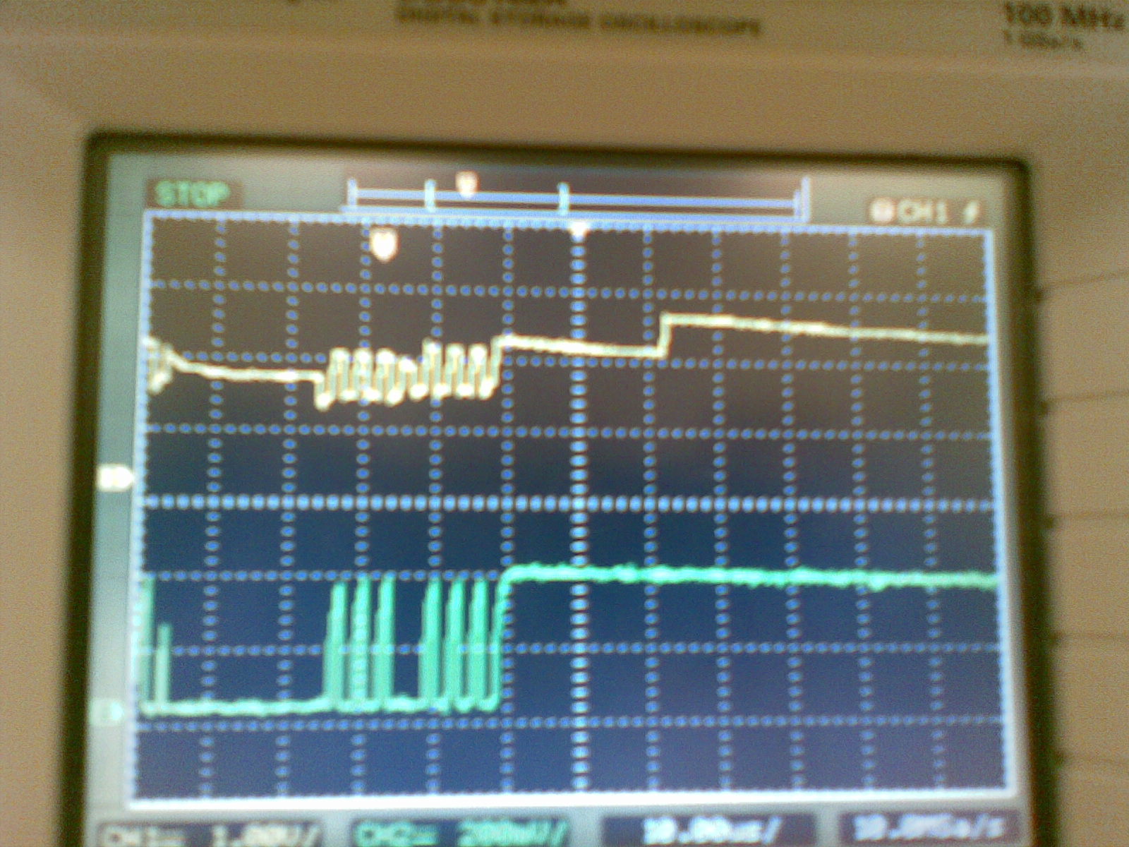
Data before and after the comparator circuit
~Tejas
Stepper Motor
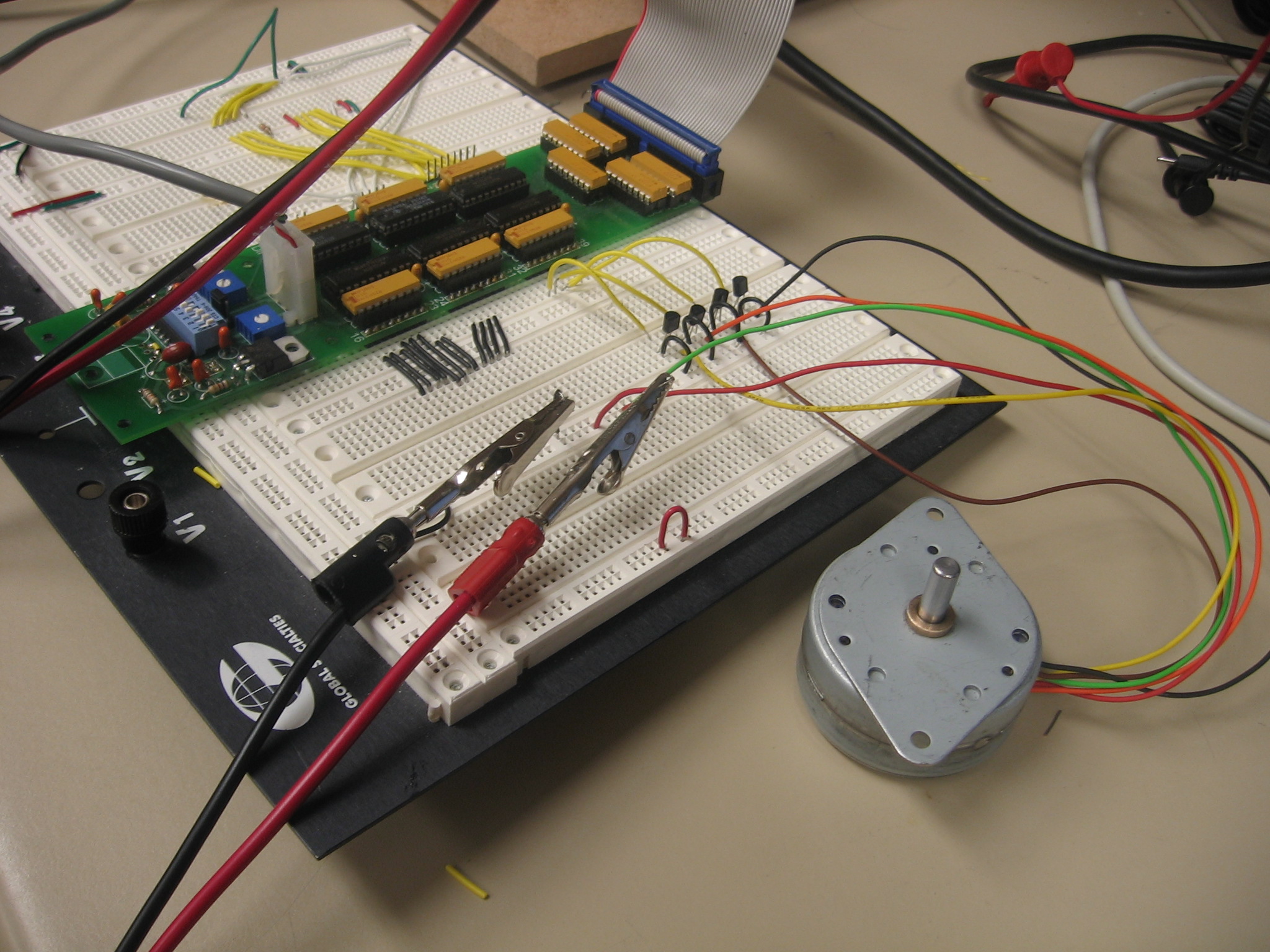
There are basically two types of stepper motor available- Unipolar and Bipolar. The one we used for our project was a Unipolar one. The operation of the motor requires 12V DC voltage and we need to send certain pattern of numbers (0xA, 0x9, 0x5, 0x6 for counter clockwise and vice-vera) through the four different wires. With each part of the sequence, the motor rotated 7.5 degrees in the required direction.
On the breadboard, we initially used a transistor for each wire, but later figured out that its much easy to use just one H-Bridge for all four wires and was much more efficient.
The picture below shows the sequence:
http://sigma.octopart.com/138143/datasheet/Danaher-55M048D2U.pdf
The H-Bridge circuit was as follows:
Chip enable 1 & 2 = Always 1(5 V)
Output X = to motor
Input X = from Circuit
Vss= logic voltage = 5V
Vs= load voltage = 12V
Hardware
The hardware consisted mainly of the address decoder to send the data to the four lines of the stepper motor. The address decoder was used to communicate with the bus and send the data to the processor. We also had to divide the clock before sending the data to the motor. As with the BUS clock the data was being sent too fast, and we were not seeing any particular motion of the motor.
Software
The driver for the stepper motor was involved taking in two arguments - The direction of rotation and the no. of steps to move. Depending on the no. of steps and the direction of rotation, we used a counter to count till we gave the motor the required steps.
Issues
We faced major issue with the calibration of our motor as everytime we would see it moving different no. of steps. We figured out that this was due to the partial memory that the motor sometimes had. So if we gave it 0xA, 0x9, 0x5 in the first go for moving it three steps, we had to start from 0x6, 0xA and so on for the next counter clockwise movement. But when we had to move it clockwise, it didn't always start moving in the direction immediately. We tried to have a memory in the software to remember the last given sequence. But this also didn't solve the problem. Ultimately we decided to move the motor back to the starting position after every move. This idea worked perfectly for us.
~ Abhishek
Graphics Controller
Hardware
The graphics was actually quite difficult to interface with. One of
the biggest issues was the fact that the graphics controller had to use
the bidirectional data bus, so ensuring that the bidirectional data bus
was operating correctly turned out to be quite tedious. We found that
many things could go wrong in
terms of interfacing with the hardware, including allowing other devices
to share the bidirectional data bus inadvertently and incorrect wiring.
Once the hardware had been completed, and it was clear that the
device was responding to basic commands, most of the work then took
place in the software portion.
Software
The most useful document for this was http://www.eecs.umich.edu/courses/eecs373/Labs/devices/DMF5005%20helpful%20hints%20by%20Jeff%20Sterniak.pdf. However, there were a few glaring omissions from the document itself. When writing graphics or text with the expectation that they will appear on the screen, it is necessary to clear the screen of text and graphics first. In order to do this, every block for text and graphics must be cleared manually, as there is no “reset screen” option that exists on the graphics controller. Once that was done, we found a program online called fastLCD http://www.fastavr.com/Downloads_act.htm. This program takes a bitmap image and converts it into a basic file. With a few manipulations for the text, we were able to put that into a format that the graphics controller could read properly.
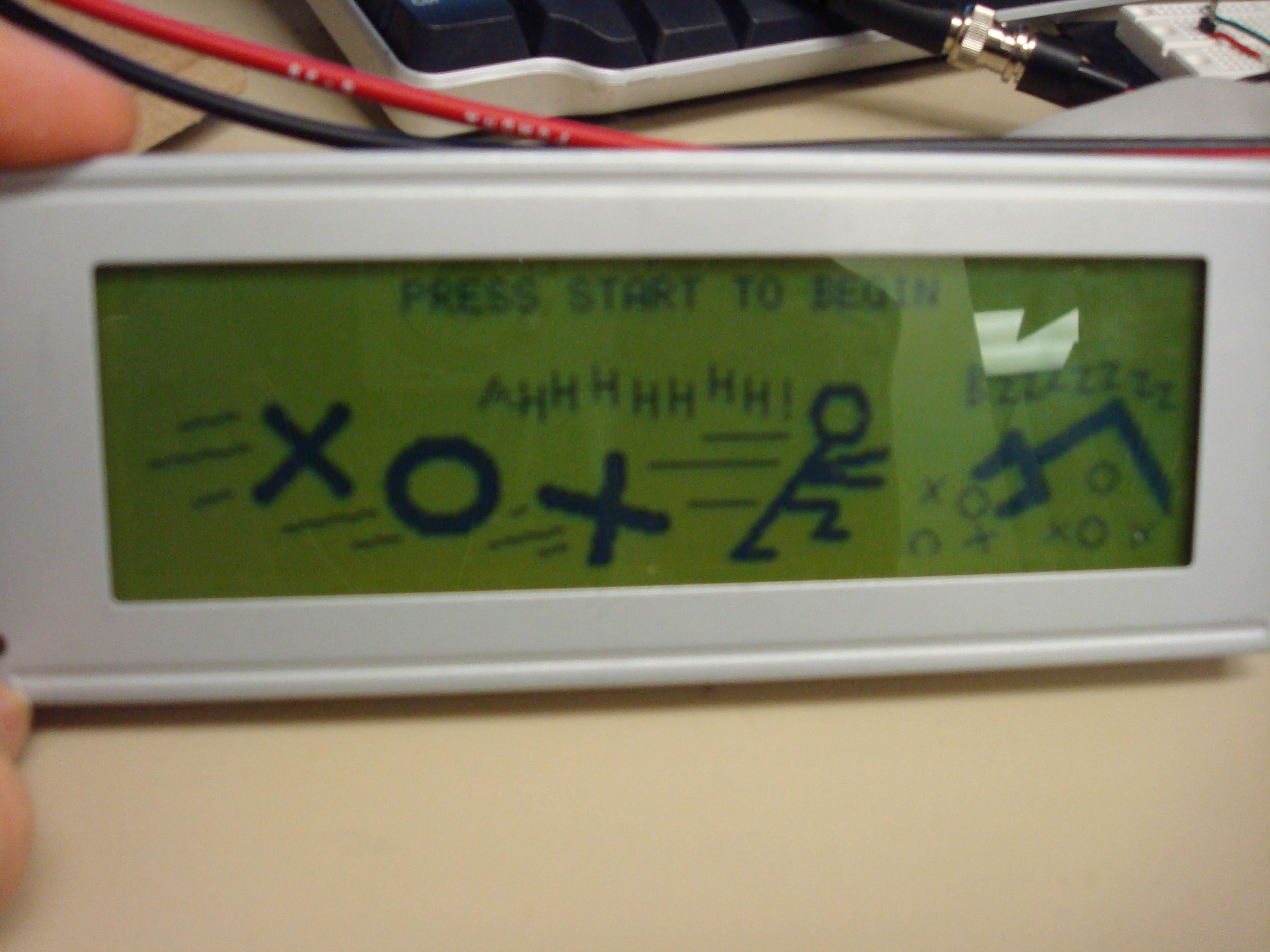
One of the effects of the graphics was that if a bad move was done, the screen would blink, similar to an error message found on many modern computers. In order to accomplish this task, we set up an interrupt to go off every second. The interrupt would then update the counter register. When a flashing graphics was to display, we would poll the counter register, keeping track of changes. The reason we would poll the counter register was because while the graphics were changing, we wanted to lock the game (so that the user would not be tempted to make bad moves for the rest of the game. We would also do this for other screens that should be seen and not bypassed, such as the opening screen and the player win screen.
~ Prakit
LED Array
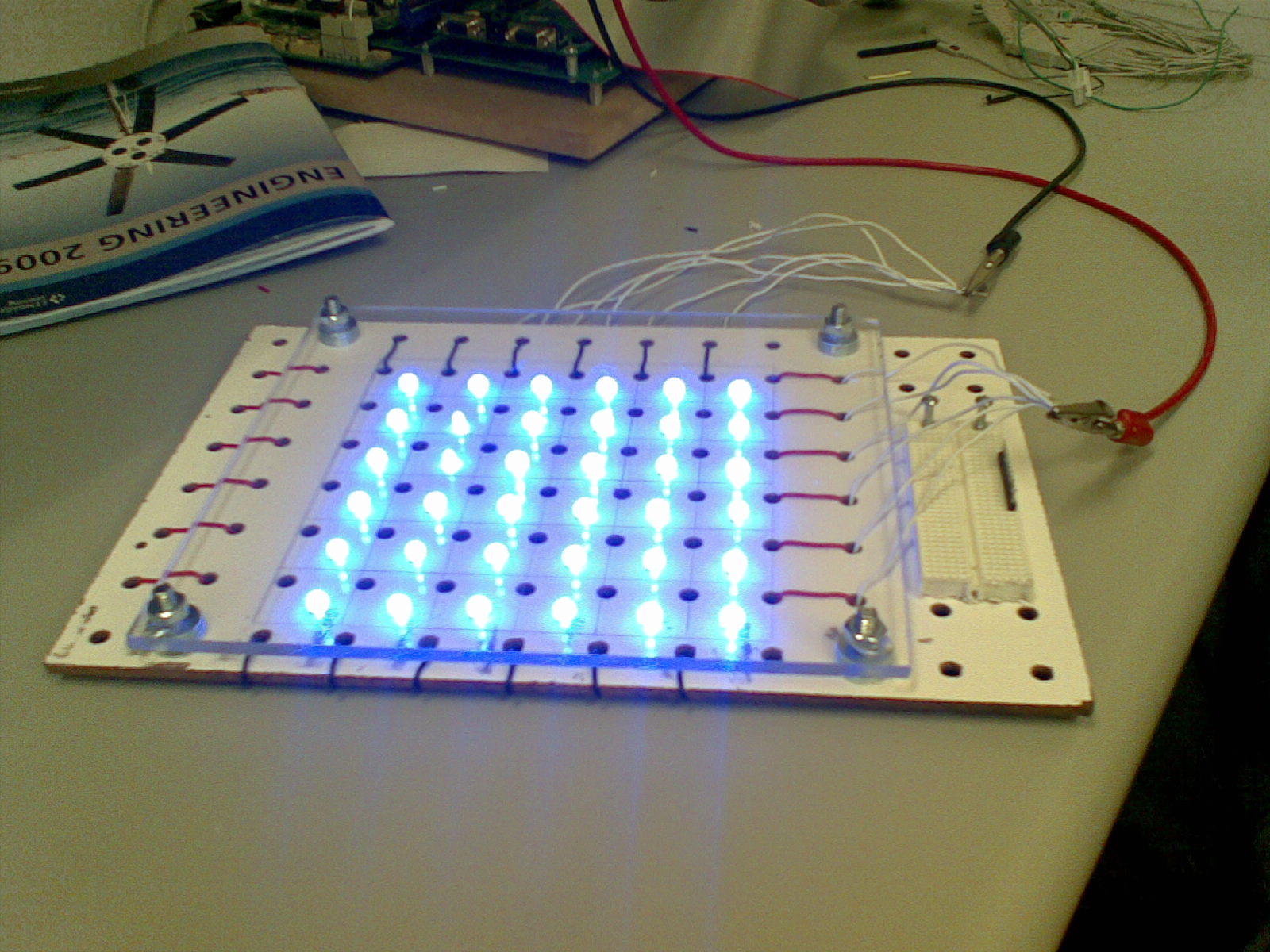 LED Array
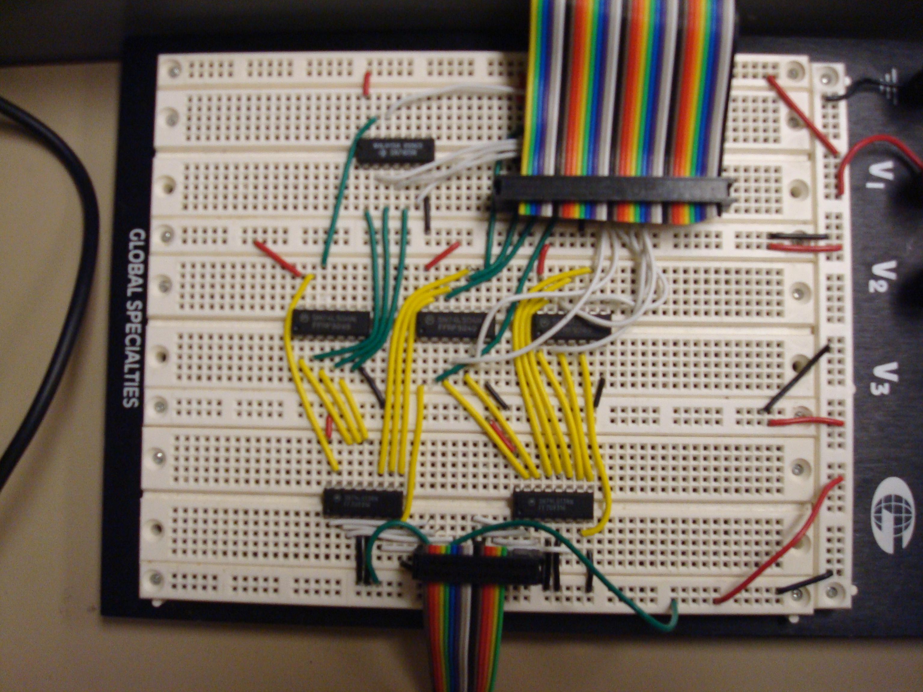
Decoder and open collector circuit for LED
array
The LED array for the project was pretty straightforward. We soldered the
necessary connections to make the 6x6 grid and used two physical
decoders on a breadboard to control the selection of the LEDs.
Hardware
In Xilinx, memory-mapped flip flops store x and y coordinate values
written to them in software software. In turn, the flip flops feed the
values continuously to the decoders. One decoder is used as a current
source while the other decoder is used to control a series of open
collectors which sink current and completes a circuit for one LED at a
time. The Xilinx hardware also features a clock divider that causes the
LED to blink once per second.
Software
The driver for the LED array was very simple. A user
simply has to input x,y coordinates into the driver which would then
write the corresponding values to the memory-mapped flip flops.
~Allen
Overall Software
Overall Software Diagram:
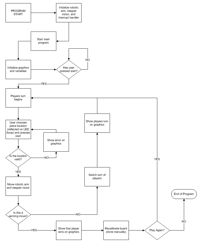
We chose to implement a software timer instead of a hardware timer
due to our specific reasons for using a timer. For the graphics, we
wanted to ensure that if a user did an invalid move, or if a player won,
we wanted that message to display and “blink” and essentially lock out
the rest of the system. In order to do so, we implemented a software
timer that would increment a global counter once a second. When an
invalid move was performed or if a player won, we would load a value
from the global counter, and then poll the value until it changed
(meaning that one second had gone by). We did this on purpose, as we did
not want the program to do anything until the graphics had finished its
job.
All of our initialization functions were done in assembly. Our main
program was done in C, as it was easy to maintain game state using an
array. The other program done in C was the program that maintained the
blinking of graphics, as it was easier to call the specific graphing
functions from C rather than assembly. In all cases where our functions
were not leaf functions, we were sure that we were following the ABI.
For instance, the interrupt handler required that we followed the ABI
and saved and restored all variables that were used by the handler
itself.