Hardware
The purpose of this page is to show how we implemented several of our high level functions in hardware.
*Display Processor: LCD Display*
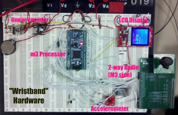
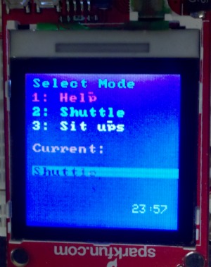
The user receives live input about their performance, on the LCD display, attached to their wrist. We utilized an LCD display (Epson S1D15G00), which received input from a linear encoder. The LCD included a control that we interfaced to over SPI.
Here is a picture of our LCD screen in action! (Main Menu)
................................... ......................................
*Processor Timer: RTC and Timer*
Our board had built in RTC and Timer capture functions, which we enabled and configured for our modified use.
*Sensors*
*Implementation of Interfaces to Sensors: Sensor Implementation*
Our sensors were implemented through SPI (x2), I2C (x1), analog with ADC pins (2 devices, 4 pins), and GPIO interrupts
**Characteristics and functionality of sensors**
- Accelerometer
We utilized a 3 axis accelerometer that sent varying analog signals to 3 ADC pins on our device. The outputs were analog voltages, proportional to the acceleration, based on the static acceleration of gravity and the person’s current acceleration. The accelerometer was used for our sit ups. - Wii Motion Plus
We used a Wii Motion Plus as a 3 axis gyroscope. This device inputs data (6 bytes) over an I2C bus. The Wii Motion Plus was used to measure the orientation of the person performing sit ups. - 2-way Radio
We used 2 way radios for communication between our two systems (M3 and M0/SmartFusion). These utilized a SPI protocol and interrupts. - Linear Encoder
Input to the device was through a linear encoder with 2 outputs. One output that determined the twist direction, and the other that was an active low button push line. - Distance Sensor
We used a distance sensor to detect the distance from one’s finger tips to the sensor. This sent an analog signal to an ADC pin on our M3 and was used for the sit and reach. - Light Break Sensor
We used a light-break sensor to detect when the runner crossed the finish line for the shuttle test. The beam was cast into a photo resistor, which was inserted into a comparator, which fed into a GPIO. When the beam was broken the photo resistor detected the change, the comparator value became 1, and our software could detect that the runner had crossed the finish line.
Here is a picture of the hardware on our Fitness "Wristband". It included the M3, the linear encoder, the LCD Display, the radio, and the accelerometer.