|
|
|
||||||||||||||
|
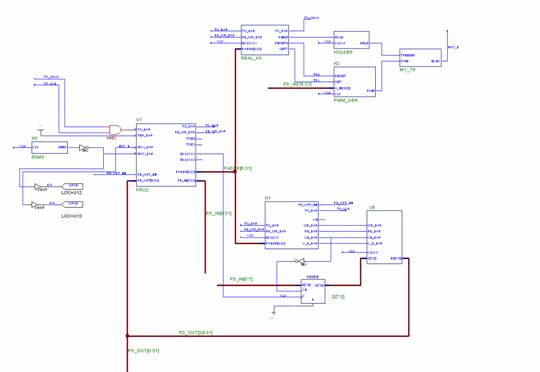
Servo: The Futaba servo provided to
us operates on pulse width modulation (PWM). At 50% duty cycle, this PWM
would look like a clock with 20 ms period. However, the duty cycle for the
servo to move hard left is about 0.6% and hard right is 2.4%, according to
the spec. These values are calibrated by us. To obtain these, we have a
hardware clock divider that outputs a clock with 10 us period by dividing the
system clock then counting up to a preset value. These 10us
“pings” are fed into a Verilog module which also takes in an 8
bit data line, a set signal and a reset signal. The module counts up to a
set number of “pings” before setting the output signal to low,
which it then sets to high after 2000 pings This set number of pings is
variable and is set by giving a value on the 8-bit data bus and applying the
‘set’ signal. The value can be anywhere between 60 (for a hard
left) and 240 (for a hard right). Upon resetting, this value is set to 150.
We use values 78-220 to sweep. A hardware clock divider and
a counter are used to generate a clock with a 50 ms period. This clock is
directly hooked into IRQ 1. Hence every 50 ms, on the falling edge, an
interrupt is generated when we execute the servo angle change Sonar sensor: The sonar ranger works
totally digitally. A 10us trigger signal is applied to a pin, following which
an echo signal goes high on an adjacent pin. At this time, an ultrasonic
pulse is sent out by the ranger. The echo signal goes low when the pulse
bounces off an object and returns to the sensor. We measure the width of this
echo signal to approximate how far the object is. The sensor is triggered by
performing a write to 0x02500000 each time the servo changes angle. This
write pulse is held for a few hundred clock cycles to maintain the 10us restriction.
The echo signal is directly hooked up to IRQ7. LCD: The DMF 5005 LCD was used to
display objects’ angles and distances with respect to the sweeping
distance sensor. The DMF 5005 LCD uses
the T6963C controller. To interface to
this controller, two modules were created. The first module decodes four addresses which are
used to conduct a “status read”, “data read”,
“command write”, or “data write”. Once the correct
address is specified, then a series of signals are generated which will
facilitate an initiation of the LCD. The second module is a direct interface
with the DMF 5005 LCD pins. It maps
the test points used on the I/O board with the addresses specified.
|
||||||||||||||