|
Our
software design had three main components, the changing the angle of the
servo, sampling of distance sensor every move of the servo, and the LCD
controller interfacing.
Initially,
in our design, we generated 1 ms interrupts which were used as the
“ping” signal to the Verilog module. Evidently, this gave very
poor resolution since the PWM itself is 20 ms. Next, we tried to create 10
us interrupts to emulate what ended up being our final design. However, we
realized that all of the interrupt and test C code (calculator) took about
47 us to execute, hence creation of 10 us interrupts was impossible, in
addition to being inefficient. Now, as mentioned above, we use a hardware
clock divider to generate 10 us interrupts and feed it to the Verilog
module.
We
control the servo by changing the angles based on current direction and
angle. A hardware clock divider generates a 50 ms clock, at the negative
edge of which, an interrupt routine is called. In this interrupt routine,
we change the angle of the servo by 2 ‘degrees’ based on the direction
it is currently sweeping in. Similar to the lab in which we had a bouncing
LED light, we bounce the servo when it reaches a preset limit.
Additionally,
each time the servo changes angles, a distance sensing transaction is
initiated, and a 10 us trigger is maintained into the SRF04 distance
sensor. By initiating this trigger when the servo moves, the servo and
distance samples remain synchronized. When the trigger is created, counter
2 starts counting by GCLOCK2/16. When IRQ7 (echo signal goes low) is
called, the value in TCN2 is read, stored as the ‘distance’
with the associated angle in a 2x150 array, and then reset.
To
display the data onto the graphical LCD, we designed a generic algorithm
which could be used to conduct all writes to the LCD. We assigned two pixels on our LCD for each
sample. Since each write to the LCD is 8 pixels wide (1 byte), we wait
until 4 samples have been taken to refresh a column on the LCD, translating
into 8 pixels. Using 80 samples, we wrote a recursive algorithm to write to
the entire screen. The LCD writing is done via C code, which calls smaller
assembly functions. Since writing to the LCD in a circular fashion is
virtually impossible without sin() and cos() functions and with the write
limitations of this LCD (slow; cannot be refreshed fast enough; is not
direct representation of memory bitmap), we amplify our samples as a
function of the column number (which is a function of angle), to make the
samples look circular.
The
initial mode, “Sonar Mode,” uses the functionality of the
sweeping servo to sample distances within the 140 degree field. In the
second mode of the system, “Static Mode”, we set the angle of
the servo to a static 90 degrees (looking straight ahead), but continue to
take samples and display it on the screen. This way, the device can be used
as a distance sensor when held in any direction.
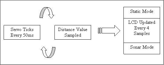
High Level
Flow Chart of the Software Design
|