|
Project Overview
High
Level Design
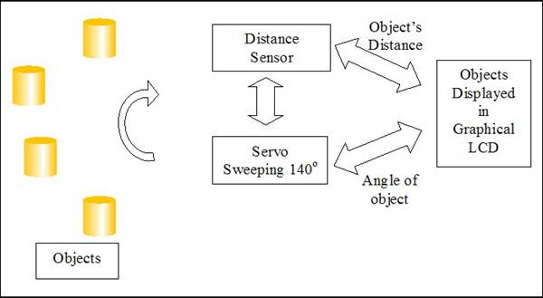
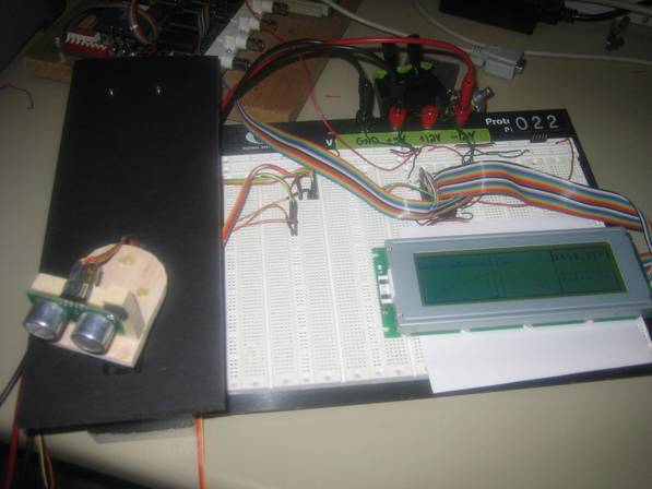
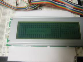
We integrated a sweeping servo, a sonar distance sensor and
a 240x64 pixel graphics LCD module to build the Sonar Ranger.
The servo is mounted atop a cardboard box. This servo sweeps
from left to right at the rate of approximately 2 degrees every 50 ms; the
range of movement is 140 degrees instead of a full 180. The distance sensor
is mounted atop the sweeping servo (perpendicular to the field of movement)
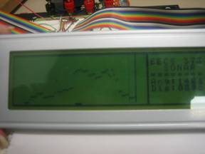
and takes a sample each time the servo changes its angle. These
objects’ angles and their associated distances are stored in an
array, from which we plot them on a graphics LCD module.
Block
Diagram of Design
Click here to view media clip
of sonar ranger in action!
Problems
Servo/Distance sensor
Firstly,
figuring out an efficient way to sweep the servo was difficult. As
mentioned above, we tried three different ways (software, hardware/software
and all hardware) to implement the pulse width modulation. Finally, if we
triggered the distance sensor and the servo out of sync, the sweeping
became extremely jerky.
LCD
Both,
initializing the LCD as well as determining the best algorithm to write the
pixels on the LCD was tricky. It took us tome time to understand the
pattern required to get the LCD in the same initial state repeatedly.
Other
We
wanted to have a hyperterminal interface to
change the mode from “Sonar” to “Static,” but to do
this, we had to put our hypterminal user input
check within our interrupt code, which had a drastic effect on all of the
timing aspects of the program, therefore sampling information incorrectly.
Writing so much information to the LCD using C code etc. took a lot longer
to execute and put everything out of sync.
Conclusion
In conclusion, we really enjoyed designing this Sonar
Ranger. The problems we encountered were challenging in nature and
certainly improved our engineering perspectives. We had all of the components
that we needed and appreciate the help received by all of EECS 373 staff.
If given the time, we would really want to figure out a way to write to the
LCD in a circular fashion as well as a way to implement the hyperterminal interface for changing modes.
References
“DMF5005 Helpful Hints” by
Jeff Sterniak
http://www.optrex.com/SiteImages/PartList/DRAWING/ue_32883.pdf
http://www.optrex.com/SiteImages/PartList/SPEC/5005cne.pdf
http://www.optrex.com/pdf/Dmf5000_full.pdf
http://www.eetasia.com/ARTICLES/2001SEP/2001SEP03_MPR_MSD_AN.PDF
http://www.densitron.com/editor/pdfs/t6963appnotes1995.pdf
http://www.chipcatalog.com/Datasheet/80B33697DCF427D683447C2D9A46BDE4.htm
|