

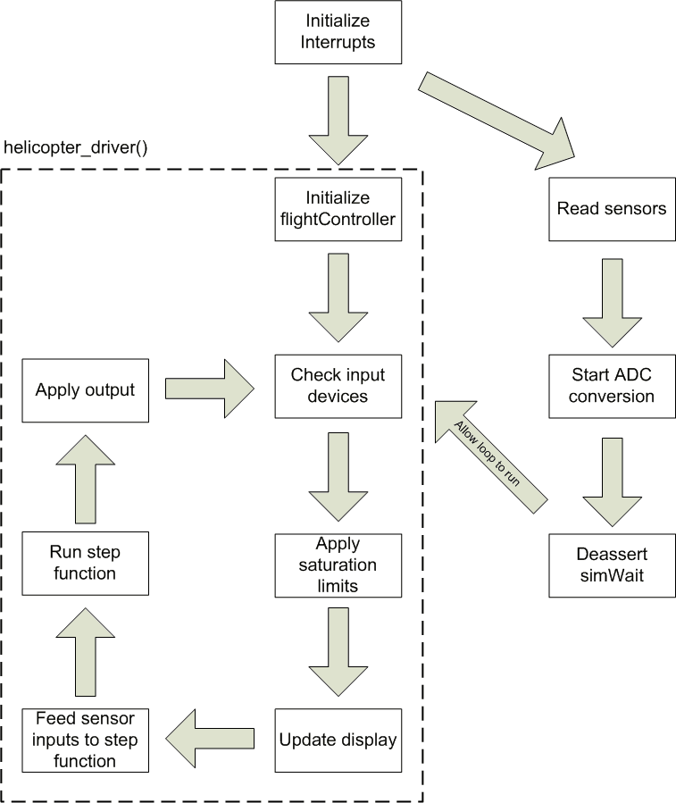
The software consisted of one main loop responsible for controlling the helicopter and LCD display, several periodic interrupts to service the sensors, and interrupts driven by button presses on the human interface devices.
Control Algorithm
The control algorithm was developed in Simulink. The Simulink model was then generated into C code using Real-Time Workshop. This provided a unit step function, which we ran periodically in the loop. In order to run the step function at fixed intervals, a global variable set by a software timer-driven interrupt would be set to true. The Simulink model can be seen in the following screenshot:
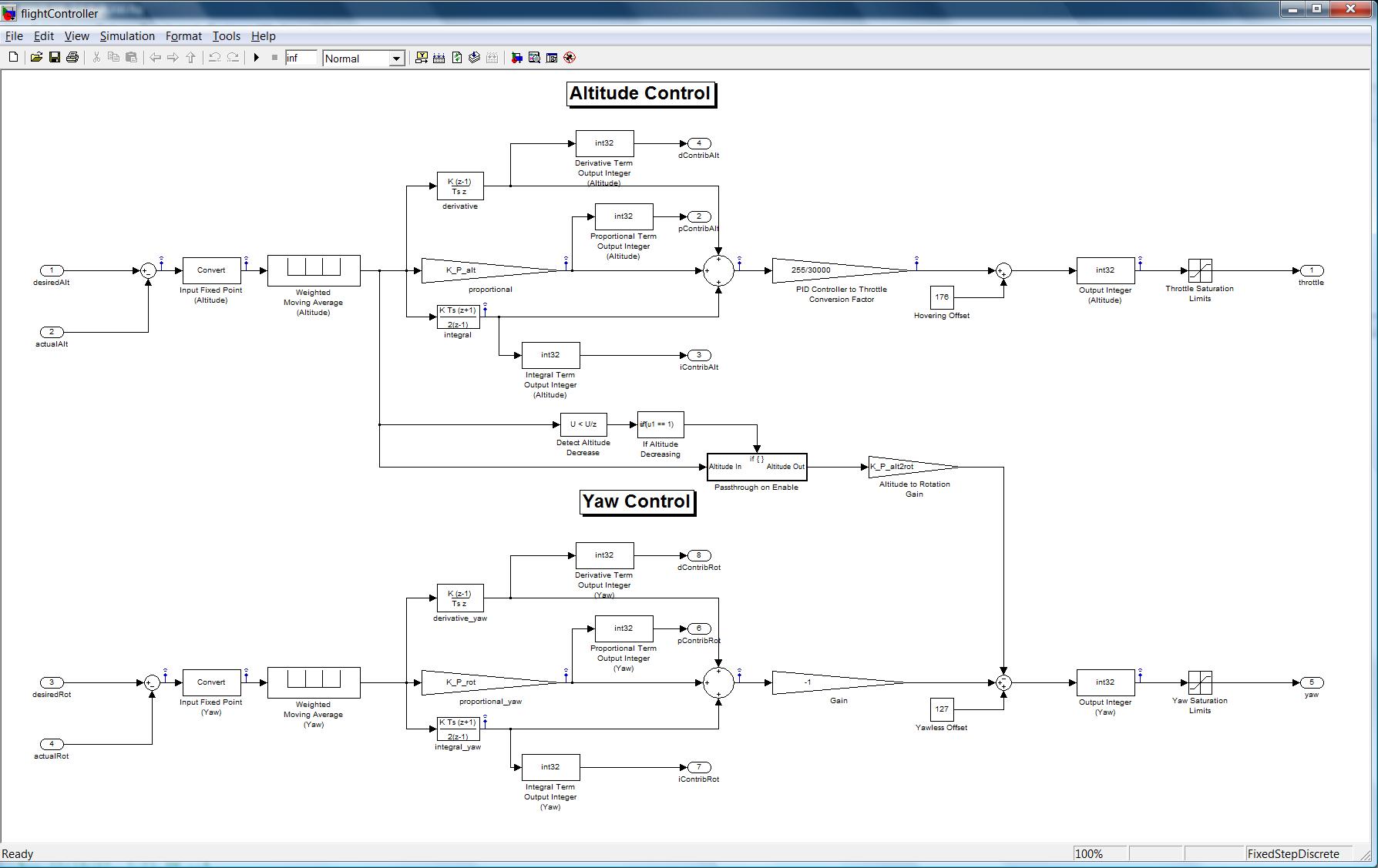
The Simulink model file:
In essence, the control algorithm is two PID-controllers implemented in software. A moving average filter sampling the last four units of time helps protect against erroneous values retreived by either of the sensors. Since the MPC823 processor does not support floating-point, a fixed-point data type was used for all of the system's calculations. Another feature of the control system worth pointing out is the feedforward term from the throttle control to the yaw control. In testing, it became apparent that any time the helicopter descended, it had a tendency to yaw to the left. To counteract this tendency, a data path from the altitude controller to the yaw controller was added.
LCD Display
Several wrapper functions were implemented masking the more complex memory operations necessary to manipulate the data on the LCD screen. We wrote a quick LCD interface library in C called LCD_tools. This provided functions to easily write a word or number at a specific position on the LCD screen. More complex methods that we created automatically displayed a bouncing word or a "flying" helicopter. These were not used in our final project. The highest level method that we actually used was called display_flight_info which took in a flight data structure and displayed all relevant information on the LCD screen in an orderly fashion.
Interrupts
The main interrupt that we used was a 25ms interrupt generated by timer1. The handler routine for this interrupt would read the distance sensor and gyro sensor data into global variables currentAlt and currentGyro. It would also initiate a new ADC conversion by writing to the appropriate memory mapped address. Finally, it would de-assert a guard variable called simuWait. This would effectively tell the control system it was ok to perform another step.
The only other interrupt that was used was an IRQ1 interrupt tied to the B button on the Nintendo controller. This interrupt handler would set the helicopters throttle to slightly below hovering speed for 2 seconds before shutting off the engines completely. The system would then be reset. This was basically an emergency shut down button.
Processor Speed
At one point, we determined that we had more code running than the processor could handle in a single period. To remedy this problem, we optimized some portions of our code (namely the LCD display wrapper functions) and increased the clock speed of the processor from 20 MHz to 24 MHz. 24MHz was chosen because it was determined to be the fastest clock speed we could run the processor at without adversely affecting the timing logic we had hardcoded into our hardware.
Data Logging
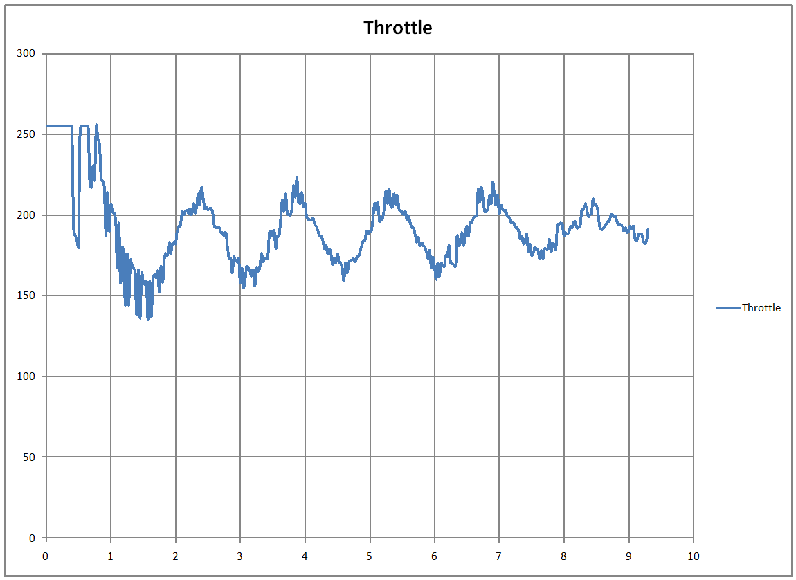
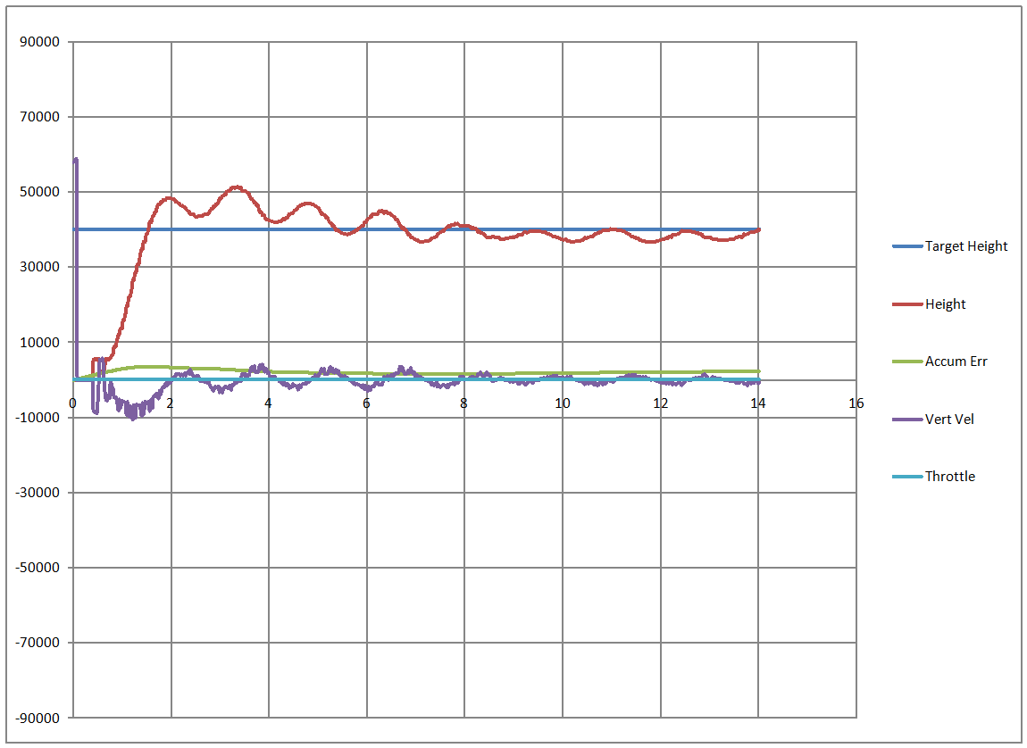
In order to better tune the helicopter, logs of the helicopter's sensor data as well as information on the controller's behavior was output to a PC via a serial port. A few sample graphs of data can be seen below:
Copyright © 2007 Nicholas Fish, Matthew Siembor